Mechanical Design of Machine Elements and Machines
This covers the fundamental principles and techniques used in the design of machine components. It is divided into several chapters that discuss various topics, such as the selection of materials, stress and strain analysis, fatigue, and shafts. This can be a useful reference for engineers and stu...
TEST BANK FOR Mechanical Design of Machine Elements and Machines A Failure Prevention Perspective 2nd Edition By Jack A. Collins, Henry R. Busby, George H. Staab
All for this textbook (2)
Written for
Mechanical Engineering
All documents for this subject (142)
Seller
Follow
jdpxx
Content preview
TOPIC NO.1 where
ANALYSIS OF SIMPLE STRESS F = applied load
L = original length of the member
This topic includes the following: A = original cross-sectional area of the
1.1. Tensile member
1.2. Compressive δt = axial elongation
1.3. Shear or Torsion σt = tensile stress
1.4. Bending or Flexural E = modulus of elasticity
(Esteel = 30x106 psi)
A machine or machine member is usually
designed to perform its function for a specified 2. COMPRESSIVE STRESS. By reversing the
length of time (operating life). In many machines, directions of the loads in the tensile stress,
the members must be able to resist external forces, a compressive stress will be induced in the
called applied loads, and, in addition, they must member. The stress formula above can be
satisfy rigidity requirements. The machine designer used provided that the length-to-area ratio
must reach decisions concerning the nature of of the loaded member is sufficiently small
action in the member that may cause it to fail, in that it acts as a compression member
order to determine what quantity or quantities without tending to buckle.
should be expressed in terms of the loads and
dimensions of the member. This generally entails σc = F/A
the consideration of the loads applied to a member δc = FL/AE
and some quantity, such as stress, strain, deflection, δc = axial
or energy which characterizes the action that may contraction
cause its failure. (From Paul H. Black and O. Eugene
Adams, Jr., “Machine Design” 3rd edition, McGraw-
Hill Kogakusha, 3. BEARING STRESS. Bearing stress differs
Ltd.,1968) from compressive stress in that the latter is
the internal stress caused by a compressive
force, whereas bearing stress is a contact
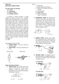
TWO PRIMARY TYPES OF STRESS: pressure between separate bodies.
A. NORMAL STRESS, σ, the area is normal to
the force carried
B. SHEAR STRESS, τ, the area is parallel to the
force
Normal Stress Shear Stress
F
4. SHEARING STRESS. Or tangential stress is
produced whenever the applied loads cause
one section of a body to tend to slide past
A its adjacent section.
4.1. Single Shear
F
SIMPLE AND DIRECT STRESSES
1. TENSILE STRESS. The average tensile stress
induced in the body of a simple tension
member in which the tensile load is
perpendicular to the surface that produces
4.2 Double shear
stretching of a material.
σt = F/A δt = FL/AE
, Shear Deformation MAXIMUM TORSIONAL STRESS FOR A ROUND
SHAFT
δs = shear deformation
G = shear modulus of 𝟏𝟔𝐓
𝛕= (𝐟𝐨𝐫 𝐚 𝐬𝐨𝐥𝐢𝐝 𝐬𝐡𝐚𝐟𝐭)
elasticity or modulus of 𝛑𝐃𝟑
rigidity
δs = FL/AG 𝟏𝟔𝐓𝐃
𝛕= (𝐟𝐨𝐫 𝐚 𝐡𝐨𝐥𝐥𝐨𝐰 𝐬𝐡𝐚𝐟𝐭)
𝛑(𝐃𝟒 − 𝐝𝟒 )
Relationship between G and E
𝐄 ANGLE OF TWIST (TORSIONAL DEFORMATION)
𝐆=
𝟐(𝟏 + 𝐯)
𝐓𝐋
𝛉=
v = Poisson’s ratio of material ( typically 0.25 to 𝐉𝐆
0.3 for metals where
P = 2πTn
5. Thermal Deformation and Thermal Stress
δT = α L ΔT (+) for heating
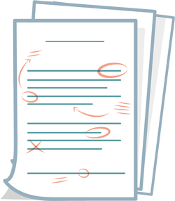
(-) for cooling 7. BENDING OR FLEXURAL STRESS. The
normal stresses induced in straight beams
α = coefficient of thermal expansion by bending are a particular distribution of
L = dimension of the member tensile and compressive stresses.
ΔT = change in temperature
Note: If the above deformation is
prevented to occur due to some restriction, 𝐌𝐜
said deformation is converted to a load 𝛔=
𝐈
deformation. The member is then under a
thermal stress, σT. M = bending moment
c = distance of the stressed fiber from the
δT = α L ΔT is equal to δt = FL/AE, where σ = neutral axis
P/A; thus, the resulting thermal stress is I = rectangular moment of inertia of the beam’s
σT = E α ΔT cross section from the neutral axis
6. TORSION. Torsional moments induce shear
stresses on cross sections normal to the axis
of bars and shafts.
TORSIONAL OR TWISTING STRESS
τmax = Tr/J (at the outermost surface of
shaft)
The benefits of buying summaries with Stuvia:
Guaranteed quality through customer reviews
Stuvia customers have reviewed more than 700,000 summaries. This how you know that you are buying the best documents.
Quick and easy check-out
You can quickly pay through credit card or Stuvia-credit for the summaries. There is no membership needed.
Focus on what matters
Your fellow students write the study notes themselves, which is why the documents are always reliable and up-to-date. This ensures you quickly get to the core!
Frequently asked questions
What do I get when I buy this document?
You get a PDF, available immediately after your purchase. The purchased document is accessible anytime, anywhere and indefinitely through your profile.
Satisfaction guarantee: how does it work?
Our satisfaction guarantee ensures that you always find a study document that suits you well. You fill out a form, and our customer service team takes care of the rest.
Who am I buying these notes from?
Stuvia is a marketplace, so you are not buying this document from us, but from seller jdpxx. Stuvia facilitates payment to the seller.
Will I be stuck with a subscription?
No, you only buy these notes for $8.49. You're not tied to anything after your purchase.