Summary Unit 6 - Microcontroller Systems for Engineers - Exam written Revision Guide
273 views 1 purchase
Course
Unit 6 - Microcontroller Systems forEngineers
Institution
PEARSON (PEARSON)
Book
BTEC National Engineering
Unit 6 - Microcontroller Systems for Engineers - Exam written Revision Guide is a revision guide directly from the assignment markers at PEARSON it has all information set out clearly in an easy-to-read format to ensure that you achieve a distinction grade in your exam in MAY. However, if you are i...
Unit 21 - Electronic Measurement and Testing of Circuits Unit Spec Revision Guide
Unit 22 - Electronic Printed Circuit Board Design and Manufacture Unit Spec revision Guide
Unit 19 - Electronic Devices and Circuits Unit Spec Revision Guide
All for this textbook (28)
Written for
BTEC
PEARSON (PEARSON)
Engineering 2016/2017 NQF
Unit 6 - Microcontroller Systems forEngineers
All documents for this subject (3)
Seller
Follow
JuliusCesar1
Reviews received
Content preview
Bad a look 0 Nearly there 0 Nailed it! 0 Bad a look 0 Nearly there 0 Nailed it! 0
icrocontr llers a Co par· g d ·r ere t
•
In this_unit, you _wilf revise how to program or code microcontrollers to solve engineering problems .
.What _i.$...a....m.ie.r.oe.9:nJroUe.r?... Barjfware_and software
erocon ro ers
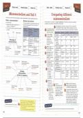
A microcontroller: Mk:rocontrolter5 ·are··avai1able in arrange of specifications: The ·tabletietow 5hows ··s·ome irrrportant ··
The only acceptable microcontroller hardware and properties of one typical microcontroller from each family.
• ·· confains··~Hn:lie.internal ·compone·nts c>ra ··· ·proqramrrring··tarrgoag·e s·for·Unit··G are·strowrr·irr·
computer on a s ingle chip the table below. The processor is the primary component of the microcontroller.
• runs a stored computer program that controls For the Genuind™ fam ily a range ·of·different processors·areused;
a system.
Hardware Software Programmi~ The processor speed The other microcontrollers are based on specific types of processor.
dev;ce family I~ lang11a43e indicates hew fast the
-'/--Rea~
Development system will operate. Hardware family GenuinoTM PICAXE9 PIO'
Environment Program memory 1 Processor ATmega328P PICAXE18M2 Genie 18 PIC18F14K22
····· Cttea
r--
p -·"-"-------'-S
i_a_ll _ _ ally available
(IDE) is sp~9e available
2 Processor 16 ··32·· 16/32 16 I 31
Arduino™/ Arduino™ IDE ArduinoT"' C or to store the
speed
···· ··· Advantages··or Genuiao™ or Flowcode Flowchart .. software.that ..
determines how 3 Program 32 2 10 16
PIC®
1---microcontrollers
MPLAB® IDE C or Flowchart
the microcontroller Memor:y
(MPLAB~ C) or
operates. (kilobytes)
flowcode
Have low power RAM is used to 4"·Rando-m Acces-s- 2048 512 256 512
Economical for PICAXE® PICAXE® Editor BASIC or
consumption Memory (RAM)
developin'3 proC:lucts store the data used
Flowchart.
and systems by the program. 5 Interrupts 2 8 8 10
... .. ... Can.be. . pr~r.ammed. GENIE® GENIE® Studio BASIC or
or Circuit Interrupts a11ow the ·G··Stack- Unlimited·· ·8- -32 ·31
to control products flowchart
and systems Wizard normal operation of 7 Typical £2.39 £2.77 £1.36 £1.61
·------- ----------------
tfie.program fo··"be ···
altered in response
to an event.
processor cost
8 Digital input Up to 14 Up to 16 6 Up to 17
capability
Input and output devices The stack- determines
Selectin<a hardware 9 Digital output Up to 14 Up to 16 9 Up to 17
(pai:ies 178-187L_ devices and system desi<an the se'luence in
ca__pability
··· ··· ...... (pa/g·e; ·,a8-l 90) ~ Assemblln<a and operatin<a which some parts of
10 Analogue to 6 10 3 12
a program operate.
Control hardware ~- a microcontroller system
Each of the
f-··
cttgitaHnputs ·
(pa<ae~ 174-178) r--"----------'--------=~ (pa<aes 191-192) 11 PWM outputs 2 8 4
Revising considered PICAXE® Genie® DM1'64130-
microcontroller ~ro<arammin<a techniques bythis unit Cli-1-030 ··· f'GB1IB · -9-f'IGlcit-low-···
(pa<aes 193-204) is available Project E18 Pin Count
system.uor e_ngineers
-/
Documentation
(pa<ae 22G) ~Co'"••=-· (pages 205-217)
in a range o f
specifications.
Inputs allow
. devices; such
When the
·Board ·· ·Activity -· ··oemo-Boara· · ·
Kit
PWM (Pulse Width Modulation)
System development
processces
(pages 221-225)
I
Number systems Structured pro13ram ·
microcontroller.
Outputs allow
mi(frocontroller needs
to connect to sensors
that measure analogue
allows the digital microcontroller
to simulate an analogue output.
desi<an (page 218) A microcontroller processor needs to
(pa<aes 219:::220) devices, such . .. variables (such as connect to· other ·components· in order·
as light-emitting temperature), analogue to become a functional system. The
diodes-,--to- .. ..to ~itat conversion-- most··c:omrrion metlioc:f is-·to Tnse-r t tlie·· · ··
-----~--- ... .._._..._._...._
------~-~--- ---- -----
be turned on
and ·off by-trre·-···--
inputs need to be used. microcontroller into a project board
············ ····· tii".if"<:iontaln5 tiie ..otfier.componeiit5 ·
microcontroller. needed. Boards are available in a
You can also refer to the followin<j documents, .rang;; ~f ~p~~ift~ti~~; t~ ~~it th~
which are kept up to date on the BTEC Nationals ....microcontroller ancUts . ap.plication~
En0ineerin<j page of the Pearson website: -
Identify any priority areas for your revision.
• Unit G: Mlcrocontroller Systems for Engineers Now try this
unit specification
• Unit G: Sample Assessment Material (SAM). Using a detailed specification from the internet for one microcontroller, revise the important properties.
172
173
, 0 0 0 0 0
•
Bad a look Nearly there Nailed it! 0 Bad a look Nearly there Nailed it!
.
Project boar s Using 0 charts ·-
-You :can .use micro':'ntroUer. project .boards ..to.easily connect.the microcontroller to.input and output .......When designing. .a .system,. you . wiU ..use .flo.wcharts.. to.p.roduce .a microcontrolJer program by ..placing..and.
devices. Some project boards allow the microcontroller to be programmed on them. connecting symbols.
Project hoards Common symbols used in a flowchart
······· ······· · ·Breadboard5-provide-·a quick-way to test-a temporary -system; The shapes of the symbols used· in flowcharts are· specified ·by 55 4058:1987, 150 5807·:1985;· The ·
• The project boards shown here provide one example for shapes and meanings of some of the most common ones are shown.
each of the microcontroller platforms. There are many
others available. The different styles of board reflect the
Terminator - this indicates the
start or stop of-the -program. D Call - directs the flow of the
...program.to.a separate subr.outine.
0 Input or output - of data.
different uses they are intended for.
--+--
··· ·--········ ..:. • · -At-one end- of the- rafl~;·· the-GENl-f~- board--forms--a ..
permanent microcontroller system where the user
connects their own input output ·devices;· At the other end ·
D Process. -::: .a pro.cess.or operation
is carried out. <> Decision - perform one of two actions
depending on the result oI the decision.
Flow lines - these control
· the program·sequence:
of the range, the E-blocks system is intended to be used
as part ofa trafriiiiq package.
Example of flowchart
Call: this directs the pro'3ram 5utn-outine: the
S t a r t - - - - - --
to the U'3ht1 subroutine. symbols below define
Output: this the subroutine Ught1 .
tumsallthe ~
outputs off fi5'\ Comments: these
before the main Vi:/ eicplain to a reader
pro'3ram starts.
\
Decision: this sin'31e
symbol combines
several functions.
First, it reads the
Arduino™ project boards are supplied assembled, analo43ue to di'3ital
ready to use. Wires are inserted into the header The PICAXE" experimenter board includes convertor.
sockets on the microprocessor and conneded to Second, it compares
a range of input / output devices built onto
components on the breadboard. this value to the values
the board. You can connect them to the specified. In this
microcontroller via the breadboard using wires. instance it tests to
see if the value is less
than 75.
Lastly, a decision on
how to proceed is
made. If the answer
is yes the pro'3ram
flows to the ri'3ht. If
The PICkit 3
the answer is no the
system consists of pro'3ram flows down. @
the programmer and
a project board.
I
Retum: this directs the flow
The E-blocks system is made up of two of the pf'0<3ram back to a
Flow lines: this
position just after the call.
c~mponents. the programmer and the project board, section is a loop
lh1s develop ent board provides an e t . that causes the
f . x e ns1ve ranqe
o input/output devrces. E-blocks are mt:ended l:o be pro'3ram to repeat
used as F'art of a training package. They uld not continuously. ®
be built into a worklng system. -----~------_, , Example flowchart from GENIE"
-
Now try this --------- --------- -
Now try this
_. . . ~----::1111----
Y~u are designing a device to control an alarm system. List the advantages of using a project board for one of the
m1crocontroller platforms. Record other flowchart symbols that are used to write microcontroller software.
174 175
, D -
D D D D D
•
Bad a look Nearly there Nailed it! Had a look Nearly there Nailed it!
· ..
ASIC as a programming C asa pro ra ming Jang age
language C is a structured programming language that is widely used to write computer software. One of the
reasons for its popularity is the efficient machine code it produces.
BASIC stands for Beginner's All-purpose Symbolic Instruction Code. You can use BASIC to write Parts of a C program
software even if you are not an expert programmer._ _
C programs comprise three main parts: structure, values and functions.
BASIC programs _ A The structure of a C program refers to the way in which the parts link with each other. The
BASIC programs consist of five parts: V structure must follow the rules of the language. ---
Commands - the key words or names given to Declarations - statements that name a
Values include constants and data types.
the tasks the microcontroller can perform. variable or constant.
Functions are the components of the program that perform tasks.
Statements - lines of code that contain a Operators - used to perform
complete instruction for the microcontroller. mathematical or logical functions, or
for repeats a block of code a number of times. In
comparisons. For example, adding two Example of a C program this example the- variable pin Number starts at 2 and
Subroutines - sections of code that can be numbers, or testing if one value is less
increases by 1 until it reaches 5. The next section of
reused in different parts of a program. than another. Comments allow the writer to provide information
code sets the pin with the same value as pinNumber to
about the program. Comments start with//, and do not
an output and turns it off. for example, when pinNumber
affect the way t~rogram operates. = 2, pin 2 is set to be an output and turned off.
Example of a BASIC program Comments allow the writer to provide information about void setupO is Q) I I This is a example c.= "' r Gqt"=
the program. A comment starts with the semicolon(;) or a function that //I t 1.-ill be used ~ qhliqhi; cc!I!!!'.cn :eatu=es o: the language
Constante are apostrophe (') character, and does not affect the way the
only runs when---® vc id ) {
program operates. Comments are coloured green.
:::::-{2)
numbers, or ASCII the program I set the LEJ pins as outputs, the :er() lccp reduces che nUll'.bior c: lines rreede::l
text strings, that
do not change
~~~i:i~~ : : ~:=~: ~~g:l~~~C c~:~~";eat:ire" cf the
starts. It is used
to initialise the
3 fQr (iG pinNumber = 2; pinNumber < 5; pinNumber++J {
4 p ~r:..te:ie (pin..>imtbu , :;c::::c:-:-i; pinMode is the function that set& the microcontroller
throughout the factors, such pin to be an input or output.
program. ~in: ---·~
;~ev::~:~e:r:t~~n ;;i~~~o~~:d! ch~i~::7::::~sa.~::::i:i~h: ~~:::et~~nt:ea ~::q:~t:::i::e :a~l:~ senscrVal
~dc c.l ,bl
0
• read the. vcltaqe on pin .le .::...!ltc var.iable bl
00 ~~~~~ Of the
microcontroller.
int "ensorVal = ac,alo;;Rea·:i (AO)
(/) inc lowValue = 75;
;@
/I This de:"ines the inceqer value belcw which LED 2 will turn on
____.-@u bl<75 then l.ightl ' i f :t:l "-" l""" t:ia" 75 the" l.ight 1 as 'b1', are named / in<: middleValue =175; I/ This defines the inteqer value abcve "hich LEl 4 will turn en
The If command
allows the program
@r---- - -- - - -- - - - - - -- - - - -- - sections of RAM
int tells the program 11 This tests to see i f the A:J:: value is less than 75 analogRead is the function that
to complete i f bl<175 then 1.ight2 ' i f :tl .is le9s t!l.a::i 175 '(;he:i lig!l." 2 memory where that the following @ i:" (sensorV~l ~ lowv~:~:> { reads the value of an analogue to
different tasks goto 1.ight3 , i f cl _;__. greater tha"- 175 t:he:i l.ight: 3 temporary data can dir-.ul.,=~-e (2, """"); // This turns en LB 2 digital converter (ADC). In this
named variable is
be stored. d.:.Q"- '".:.."" (3, :c.::;;q; I! This turns off LED 3 program the value is read for ADC
depending on of an inte<aer type.
1.ightl~=----------------- :c.::;;q; // This turns cff LED 4 on pin AO, and is assigned to the
the result of @ h.i<;h 1 _. ••·.:..tc:o e n :.ED
1
Commands, such as 'high', are instruction& This means it will be
:b;ic:•:;i=i-c
the condition lmc 2 ,,witch cff LED 2 that make the microcontroller perform a a whole number in the variable called sensorVal.
being tested. In
this example, a
low 3
goto beep
• .9Witcr1 cff LED 3
• make a ,-::::.i.9e
specific task, such as setting the output on
a specific pin to be hiqh or low.
range of -32 7G8 // e~!s i~e~~:n::r;:~ ~= ~~~~~e~!u;~c-=qual t~~=;~u~~a_~ 75 an:i less tha!l 1!5
goto main to 32767. In this dogi::;.:;\=i:e{ 2, 1::;;;); // Th.iS · ~= c:: LEJ 2
J.ccp
comparison between example the variable :ii;i::~:;\=i::e (3, f!I:OE); I I This ;u...-,,,, r ..L 3
a variable and a 1.ight2: (!)- - - - - - -- - - - - -- - lowValue is assigned // This t.urns o:f [E[
if is a control structure that is - -
number constant is 1ov 1 ' -"Witch off LED 1 Label&, such as 'light 2'' are used to mark a the number 75.
considered. high 2 • sw.itch c:i I.ED 2 particular place in a program. The program used to compare two values and
// !his L:.ests cc see i : the AD:' value is equal tc It'l.C!'e than 1'75
low 3 swit.:;h cff LED 3 can then go to these places when directed. else i: (sensorVal >= middleValue) { take a particular action based on
goto beep • make: a ~81.9e :ii-;;o'O~:w:::<.::e (2, :.c;q; 11 This turns c:: LEJ 2 the result of the comparison.
goto ma.in ' lccp ::i.:..;:_ :.~~i,•r-:..-:e (3, L:~q : // This turns c!: n:.J 3
iigita:;;=i::e (4, s:r:;s:); 11 This turns en LED 4
light3: @1--- - - - - - -- Whiteepace is a method of inserting blank 32 7G8 = 2 15
low 1 ' .swito::h c£f :.ED 1 spaces into a program to make it easier to
low 2 • .switch c:ff :.ED 2 @ toc.e (5,440,250);
read. for example, adding blank lines and
high 3 ' .9W.l.t<:::h c" I.ED 3 indenting commands helps identify groups of J )
got:> beep@ ' make a ~c13e commands. tone causes a sound to be produced on an
gotc ma.in "' • lccp
output pin. In this example a note of 440Hz
beep@- ~ . is generated on pin 5 for 250ms.
sou::ld s. 4 , 155 , 25 ) Beep IS a subroutine that is
C program for Arduino™.
Goto ma.in used by other parts of the
program.
BASIC programming langua<je.
Now try this
Now try this Rewrite, on paper or on a computer, parts of the program to work to the following new specification:
The ADC is on pin A2. The value below which LED 2 turns on is 50 and the value above which LED 4 turns on is
List the parts of a BASIC program. 200. The tone should be a frequency of 200 Hz, generated on pin 6 for 100 ms.
176
177
, ••
•
Bad a look 0 Nearly there 0 Nailed it! 0 Bad a look 0 Nearly there 0 Nailed it! 0 .
Inp tan 0
•
tput ev1ces S-witc es
Ihe switches .revised on this page can be used toprovjde a microcontrollerwith a..di9ital input..signaL..
. Input. and.. output devices allow.microcontroller..systems to react.to, __ and __change_~ the environment in _
which they operate.
--- -Switches and---l>uttons --
Analogue inputs and outputs Switches can have either a toggle or momentary
These are inputs or outputs that are continuously variable·;-·· action.
• _TotatJle __ mea.n5 .thatthe ..switch wil.l __stay .. in _____ _____
Temperature change during OA seconds
0.012 whichever position it is moved to, on or off.
--Momentary means-that -the switch changes -
fl
E
..,
0.010
0.008
from on to off only while it is being acted on
-- by -the User: Tfiey-areeitnernormally -on;or -- -
i0.
8
0.006
0.004
normally off.
Switches are available with a wide range of
~ 0.002 _ options for the number of.connections they- make
or break.. The rotary switch shown opposite has
0 2 4 6 8 10 12 0.002 o.004 0.006 o.Jos 0.010 o.ou 1-2switches- that -ttJm-on in-·sequencewhen--the · · Switches and buttons are operated by a person.
Time(s) Time (s)
shaft is turned. The major dfference in these switches is the type
The graphs show how a temperature changes over time. An increase in time corresponds to an increase of movement that has to take place for t he switch
in temperature. If you could measure time to an accuracy of 10- 9 99 the corresponding temperature would to change from being on to off.
also be measureable with the same accuracy. Movement and · o rientation --- ---
switches
Digital inputs and outputs Modular input/output devices lilt switches and shock. switches can be mounted
These are inputs or outputs that have a fixed range of values. a
rn - norizOnfal or
vertical -pc>srtron.
• Tilt switches can p~_ IJs~c:::I _Cl~ _scifc::_ty_ ~-~Yl9.~?~ --- -
Nu,mb<:r of boles. drill~d
L
Example of
----
f~~ -~~~;;:.pi~~ t~~~lng off heaters if they fall over.
10 • - Shock switches -react -when---a -movemen-t--occurs -···
.., a modular
0 sensor. at 90° to their body of the switch.
...0
<+-<
0
..,....
s;:l
4 Allow you to a5semble more complex 5Y5tem5 that
These tilt or sho ck switches change fro m
z would not_ be p055ible using j u5t di5Crete _component5. o n to off, or off to o n when the object
moves from its normal orientation.
---~--_.,,..,,,,_
tep Modular devices
_Mi~r~'.'switc:Jlf!$_
The graph shows the number of holes drilled per step of a Combine all the YC>i.i only-need to 1:.now Depending on how a micro-switch is configured,
manufacturing operation. The number of holes always increases by component5 needed to how to get 5ignal5
-- it-may -react·when-two-objects--come together--or-
C:Ori-nect directly to the frorii;-or ta, the
1, not by fract"onal amounts. Either there is a hole, or there ·1s not. when they move apart.
microcontroller 5Y5tem. device.
Input and output devices Discre~e ~l\J>Ut o~tput devices :~~i:l;~~e=n~~ s:~~~-f::t:=;~~;::::~::~
• Input devices allow microcontroller systems A discrete input or output device is one that machines.
to react t.o the environment. consists .of a single component. The lever-arms Ofl--tlle--top-of--the --micro- - - Micro-switches
switch are available in a wide range of styles are designed to
• Input devices may measure, or react to,
analogue or digital signals.
~ ~ anct··si:zes·:·Thts-·is-to··a-U-ov;r the···s-witchto·b-e· ·-- detect the relative
low cost may need additional mounted in an appropriate location while still movement between
• The data from analogue sensors must be
components connected to it -i:;e-rni:fable tc» reaet fo movement~ · -- -- ·· -- - two objects.
converted into a digital format in order for
rni<:;roc:qntroll<::r.? t,q prqc:ese, the data. flexible - many may require complex circuits
applications connected to them
• Output devices cause a change in the
environment the microcontroUer operates in .
-
Now try this Now try this
Identify where sensors are used in your home; for example, in a heating system. Describe what the sensor measures Identify a range of situations where tilt and micro-switches are used.
and what the output is as a result of this measurement.
179
178
, Bad a look 0 Nearly there 0 Nailed it! 0 -
Bad a look 0 Nearly there 0 Nailed it! 0
Temperature an hu idity
Visible and infrared ight-sensing sensors
•
ev1ces The sensors described on this page can be used to turn on or off devices connected to a
microcontroller, such as a fan. They can provide information to be displayed to a user on devices such
:hte se.nsors ~e~cribe~ in this page allow a microcontroller to react to, or measure chanl'!leS in the
in ens1ty of v1s1ble or _
1nfrared light. ' " as LCD screens.
Light-dependent resistors Thermistors
• The resistance of a thermistor either increases (often used to protect circuits) or decreases (often
Lig~t-dependent resistors (LDRs) change their
used to measure temperature) with a rise in temperature.
resistance depending on the intensity of light
• Accurate measurement using a thermistor can be complex, as the resistance chancae is not linear.
that hits their surface.
• In the dark, LDRs typically have a resistance • Thermistors typically operate in
of 1 MO. a temperature rancae of -50 °C
• In bricaht licaht their resistance may fall to to 300°C. mai n :
readadc O, t:
around 4000. if t:: >50 i:he."> ?:ll.gh 1
~n.d if
• It may take several seconds for an LDR.'s A thermistor and a BASIC
An ORP12 LDR. An LDR can be read qot:o ma.in
resistance to chancae in response to light program to turn on an output
intensity.
by a microcontroller by converting the
resistance to a voltage reading.
dependent on temperature. _,_ _________ _
Phototransistors and photodiodes
- -- -
Temperature sensors
------ Environmental sensors
• Temperature and relative humidity can be
Phototransistors and phot odiodes react much • This temperature sensor is an integrated
measured with a sensor such as the DHT11
more quickly than lDRs to changes in light. circuit that outputs a voltage, which is
shown here, which produces a c:ticaital output
• A photodiode works in the same way as a directly proportional to the temperature.
si1:3nal that can be displayed on a computer
solar cell. Light that hits the sensor generates • A rise of 1 °C will increase the output monitor or an LCD screen.
a small current. A photodiode will work in voltage by 10mV. • It measures relative humidity between
1 nanosecond or 10-9 s. This predictable 20-80 % and temperatures with a range of
• Phototransistors work by light hitting performance makes
0-50°C.
the sensor, which then allows a current to it easier to accurately
flow between the collector and emitter. A measure temperature
phototransistor will typically switch between using a microcontroller.
on and off in 10 microseconds or 10-G s.
Phototransistors and photodiodes can be used A temperature sensor to turn
to detect changes in the intensity of both visible on an output dependent on the
and infrared light. temperature. This sensor operates
·1n a temperature range of -40°C
Inf rared receivers to 125 °C. It can be utilised using
·-
Data is transmitted to an- infrared receiver by addin'.3 a code to the BASIC program above.
a carrier Si<,3nal, in the same way as a radio is broadcast.
•,•: cj l:o~{) (
/ / Tt>.e :lex:: li:u~.3 =caj, the !!l~n!!lcn hwr.::..:1::..t.y a:i.1 -c~r~-:.:i:re va.:u~
:ioa: h ~ dtle.readl!umidity();
.::. o•: i: • dtle. :•d:~::;;:~:":•;:< {);
The receiver's circuitry removes the carrier si'.3nal, leavin'.3 only // The !cllc•·.!.!lq l!.ne" -..:i:.l 1.i!!11=lal' t~e ::ea:11:ig~ ~::cm t.he "en~::r
the code for th-e microprocessor ~to process. A DHT11 sensor i: (isnan(tl i ; i•n"'1(h) I (
and code for the Ii) !~:~a~ . ~::.::-.-:1~.( .. :~.: i ~d -c..:- :ec:: ~= :.:;. t ::: ");
Format lnfrared receivers are Arduino™ Uno to Serl.al . p.~.:.;.:. { "2".:.;.=•.id.<.~~· : "l:
Sec.ul.;-::::..:.:: (h) ;
The exact format of the codes is specified by a optical sensors that read and display Sena.l . ;::~: q· I : ");
rancae of protocols. Most protocols transmit the receive signals transmitted the values. ~r-1.al.p.::..rt:: (" :e:;;.·~=ai:. •..:.:~: ");
Seoal · •=~~: (t);
data by st:mding specific sequences of high and by devices such as S~-r13..l . p:1:-.:-.i:: ( " •C');
low signals. -- television remote controls.
-
Now try this Now try this
Using the internet, locate specifications ofthe components shown above to aid your revision and provide reference.
happens when the l~vel of ligh~ ch:;g:s :~~:~p~~n1bwlehly1gthh: s~nsorsd; for example, street lighting. Describe what
Think about devices or objects th t k f ·· ·
1s 1s an a vantage for the user.
181
180
The benefits of buying summaries with Stuvia:
Guaranteed quality through customer reviews
Stuvia customers have reviewed more than 700,000 summaries. This how you know that you are buying the best documents.
Quick and easy check-out
You can quickly pay through credit card or Stuvia-credit for the summaries. There is no membership needed.
Focus on what matters
Your fellow students write the study notes themselves, which is why the documents are always reliable and up-to-date. This ensures you quickly get to the core!
Frequently asked questions
What do I get when I buy this document?
You get a PDF, available immediately after your purchase. The purchased document is accessible anytime, anywhere and indefinitely through your profile.
Satisfaction guarantee: how does it work?
Our satisfaction guarantee ensures that you always find a study document that suits you well. You fill out a form, and our customer service team takes care of the rest.
Who am I buying these notes from?
Stuvia is a marketplace, so you are not buying this document from us, but from seller JuliusCesar1. Stuvia facilitates payment to the seller.
Will I be stuck with a subscription?
No, you only buy these notes for $21.33. You're not tied to anything after your purchase.